Circuit Board Repair Analysis
Analyzing, locating, and repairing circuits is the basic job responsibility of a hardware engineer. There will always be various strange and peculiar issues on-site, and we need to gradually locate and solve each one to reduce failure rates, improve production line yields, increase average failure-free time, and reduce after-sales issues. This section introduces several common analysis approaches that are universally applicable in the hardware circuits like mobile phones, tablets, and computers, below is from one of our engineers:
In everyday work, I found that some colleagues did not locate the root cause of the problem before haphazardly replacing a piece of hardware. Although the problem disappeared, the root cause was not identified, and this is always a hidden danger. If a concentrated after-sales outbreak occurs, the consequences cannot be estimated. This section introduces several common circuit problems and their analysis and rectification approaches. Once again, it is emphasized that when encountering problems, we must locate the root cause.
Years ago, I encountered a product from a certain company that uses an IMU sensor unit to detect body angular velocity and angular acceleration, also known as A+G (accelerometer gyroscope). The current mobile phones must have an IMU unit, and for products such as drones, the IMU is one of the necessary units for inertial navigation. During the trial production, they found that there were several boards with abnormal functions. Finally, it was found that the board worked normally after replacing the IMU chip, and the conclusion was that the IMU chip was abnormal. However, the company had a relatively small scale and an immature R&D system, so the problem was not further followed up.
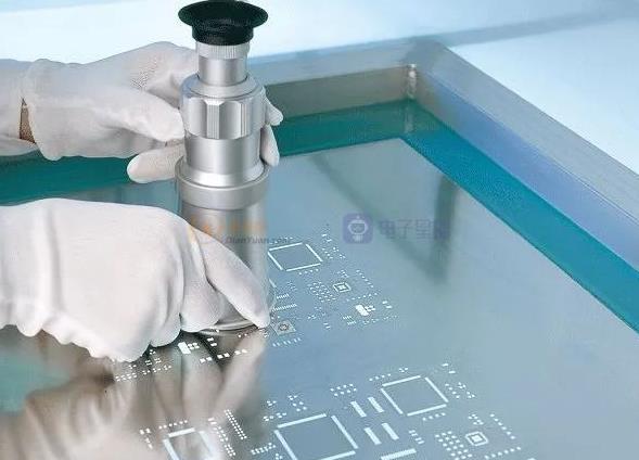
In fact, the IMU chip causing the board to malfunction is only a surface phenomenon. When I communicated with them, I asked if the chip was broken or if there was a problem with the peripheral circuit, whether it was false soldering or desoldering, whether it was caused by structural stress or electrical stress, and they couldn’t answer these questions because they did not locate the root cause. Therefore, there was no targeted modification, and this is a hidden danger. Later, I helped them form a set of R&D processes to standardize trial production problem tracking.
So, what are the usual root causes of such problems? And how can they be modified?
1. Poor soldering - short circuit
During SMT in the factory, local tin joints may occur, and the amount of tin used is not large. Therefore, the system works normally at the beginning. As the temperature rises or the board vibrates, the tin may affect the circuit, which leads to abnormal circuit operation.
2. Poor soldering - false soldering.
This is also a common soldering problem that many people have encountered. Some ICs do not work normally, but work normally after adding soldering (i.e., re-soldering), which is likely to be false soldering.
3. Vibration causes false soldering
In the process of using our PCB circuit boards, it is inevitable to encounter vibrations, such as motor vibrations in mobile phones, propeller vibrations in drones, or daily falls. These high-frequency vibrations may cause components to fall off or aggravate pin false soldering. Therefore, in trial production, in order to eliminate abnormalities caused by these vibrations, mobile phone developers often drop countless mobile phones to screen out abnormal phones and locate the problem for rectification.
4. Vibration causes chip damage.
Sometimes, this can be clearly seen under a microscope, and cracks can be seen on the surface of the chip. Sometimes, there are no abnormalities on the surface, but the chip has already been damaged internally, and the chip manufacturer needs to conduct root cause analysis. Therefore, engineers generally perform appearance and impedance tests on abnormal ICs. At the same time, engineers who responsible for structures need to analyze whether the chip is in a stress-sensitive area.
5. Chip burnout
Sometimes, this can also be observed under a microscope, but sometimes it cannot. For products with tight project schedules, the chip manufacturer and the product team need to analyze the problem synchronously and eliminate the circuit and IC problems at the same time.
6. Counterfeit chips.
No more explanation
7. The chip itself has problems.
The chip also has different production batches, and the production environment may have differences to a greater or lesser extent. It is possible that this batch of chips itself has problems.
Short-circuits and false soldering are both related to soldering, and the methods for determining the presence of short circuits or false soldering are straightforward.
Generally, re-soldering and cross-validation are performed. By adding soldering and applying flux, if the system operates normally, it is likely related to soldering. If re-soldering is not effective, cross-validation can be performed by swapping the suspected IC on the abnormal board with a normal IC on a regular board and vice versa.
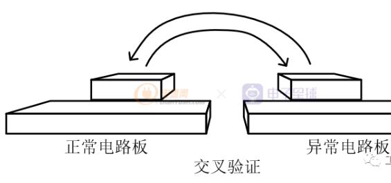
If both boards work normally after cross-validation, it is probably related to soldering.
If the system is still abnormal after soldering the suspect IC onto the board, but the abnormal board becomes normal after soldering a normal IC onto it, the problem follows the IC, indicating likely IC issues. If the regular board becomes normal after soldering the suspect IC onto it and the abnormal board remains abnormal after soldering on a normal IC, the problem may be related to the circuit board.
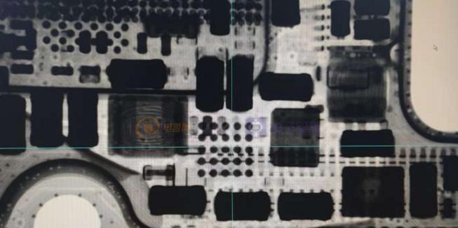
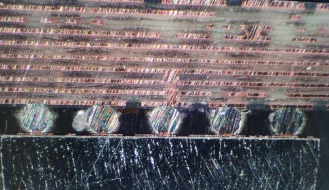
The approach to rectify soldering problems is also similar. By analyzing 3D X-rays or cross-sections of several abnormal boards, corrective actions can be targeted, such as controlling soldering temperature, adjusting the solder amount by adjusting the stencil, or micro-adjusting component position to avoid short circuits. The image below shows that the solder balls of the IC are not completely full, indicating a need for optimization.
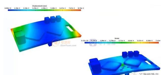
For some products, they are fine but become damaged when dropped, in which case, disassembly and analysis of the cause of the damage is necessary. Combined with the distribution of stress on the circuit board, corrective actions can be taken.
For example, large chips in glass packaging are sensitive to force. These chips should not be placed in positions where the board is more prone to twisting or subjected to higher stress. The layout can be adjusted, or reinforced fixing devices in the PCB on the other side of the chip can be added to relieve the deformation of the circuit board. Alternatively, padding can be added behind the chip for buffering.
Of course, directly changing the chip layout is the best approach. Many simulation software can simulate forces, and optimization of the layout can be done at the early stage to minimize these problems.
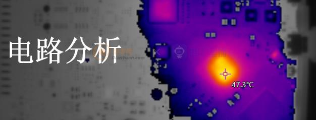
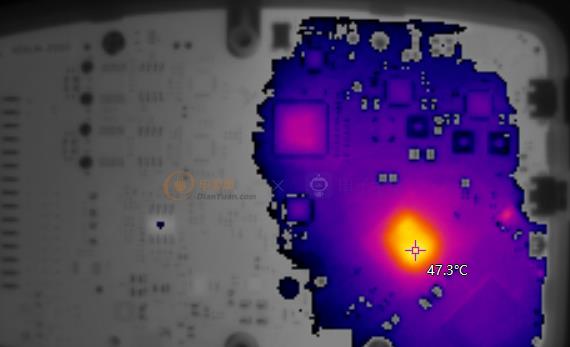
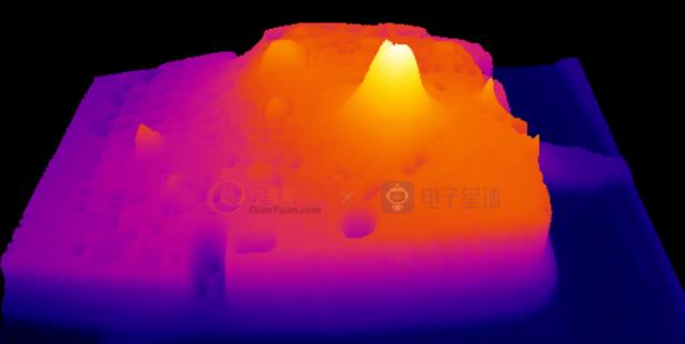
The infrared thermal imager is one of the commonly used devices for hardware debugging to locate short circuit positions conveniently.
Sometimes, when you power on the device, you can use the infrared imager to see the location of the short circuit, which is much faster than testing or dismantling components one by one.
However, sometimes the short circuit current is too small or the PMIC power module has short circuit protection, so the hot spot may not be visible.
In this case, an external power supply can be used to directly inject current into the power network with abnormal impedance to ground, such as injecting 100mA current into the circuit board (when analyzing the computer PC motherboard, several amps of current are often injected). This makes it easier to see the short circuit or breakdown hot spot.
If it is indeed a chip malfunction, we also need to analyze why the chip failed. Chips also have batches. We provide the chips to chip design manufacturers, and they analyze the specific reasons for chip failures.
We shouldn’t analyze by ourselves because everyone has their own expertise. For example, in the past, we encountered a problem with wafer contamination in a batch of a certain chip, which caused an abnormal probability of the chips in the batch.
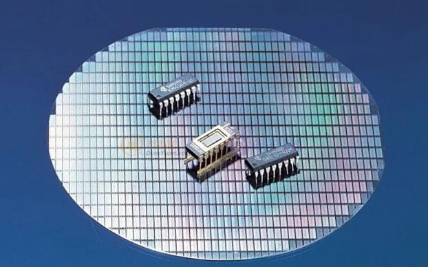
We all know that the production process of chips has special requirements for the environment. IC manufacturers can even track which position on the wafer a chip belongs to. If there is a problem with this batch of chips, they need to be isolated in time to avoid mixing problem chips with normal ones, and to manage the materials logically and reasonably.
The above is the analysis and maintenance ideas for hardware circuit boards. We hope that you don’t encounter the sixth situation, which can really be frustrating!
Our factory designs circuit boards and produces finished products, and there will always be defective products that need to be repaired. These are some repair analysis methods of engineering, hoping to help you.
