1. What is foreign object detection ( FOD ) in wireless charging?
FOD, which stands for Foreign Object Detection, is a technical detection measure used in wireless charging to prevent the system from overheating due to accidental foreign objects.
Unlike wired charging, where physical connection is required for operation, wireless charging connects two independent objects through a magnetic field, which creates the possibility of foreign objects in the path.
The foreign object here primarily refers to ferromagnetic metals. Ferromagnetic metals are themselves a closed circuit.
When these materials are placed in a changing magnetic field, the magnetic flux passing through the circuit changes, which generates eddy currents in the metal, resulting in dissipation and heating due to current flow within the metal, it’s known as the eddy current effect.
During wireless charging, a changing magnetic field exists between the transmitting and receiving ends. When a metallic foreign object is placed in this magnetic field, it heats up, and if the temperature rises to a certain degree, it can damage the wireless charging receiver and transmitter.
Foreign object detection is to detect it when a metal foreign object is on the wireless charging plate to prevent unnecessary damage from overheating during wireless charging.
Therefore, FOD technology is essential and quite important in wireless charging applications.
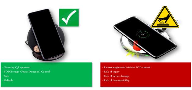
For example:
In the left picture, the charging transmitter (TX) equipped with FOD, detects a foreign object (a coin) and exits the charging mode.
In the right picture, the TX without FOD does not stop transmitting the magnetic field even if foreign objects (a coin) are present, and the coin produces eddy current heating in the alternating magnetic field continuously established by the TX, which can easily cause accidents.
2. How to detect the foreign object detection ( FOD )
There are many ways to detect foreign objects, such as by detecting power loss and Q value.
In the Qi protocol, only the temperature rise of the wireless charging receiver (RX) is specified. The certification laboratory test specifies that the RX temperature rise should not exceed 12°C above the ambient temperature.
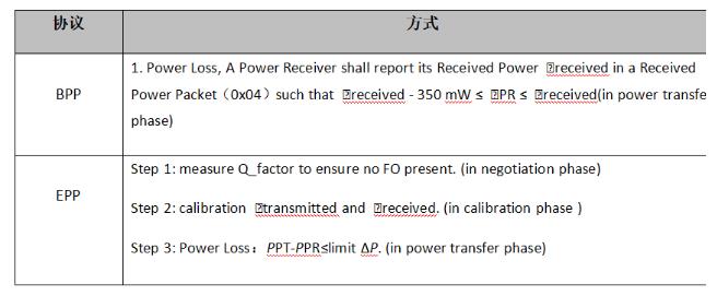
However, it does not specify which method must be used to achieve this goal. Currently, the commonly used methods are listed in the table below:
2.1 What's PowerLoss dection ?
2.1.1
( Note: For PLOSS, 300 mW is an appropriate threshold value for limiting heating of Foreign Objects )
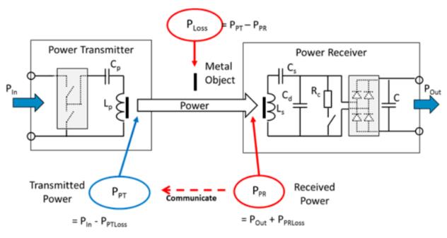
As shown in the above, the TX calculates PLOSS to determine if FOD has occurred, where PLOSS= PPT – PPR.
Where:
PPT = PIN – PPTLOSS, PIN is the input power, PPTLOSS is the necessary transmission loss power at the TX end, including but not limited to the equivalent impedance of the primary coil and capacitor, power consumption generated by the inverter circuit and PCB routing, eddy current loss and system power consumption generated by metal components at the TX end.
PPR = POUT + PPRLOSS, POUT is the output power, and PPRLOSS is the necessary transmission loss power at the RX end, including but not limited to the equivalent impedance of the secondary coil and capacitor, power consumption generated by the rectifier circuit and PCB routing, eddy current loss and system power consumption generated by the metal components at the RX end.
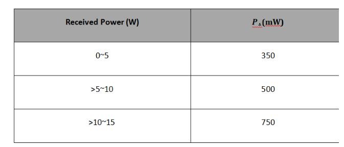
The reliability of detecting the presence of foreign objects using the power loss method mainly depends on whether the reported power from the TX and RX is accurate. Considering some unmeasurable factors such as the impact of degrees of freedom, the reported power offset between the TX and RX under different loads, and the energy that is dispersed into the air, to prevent the TX from falsely reporting FOD, the RX typically reports Preceived = PPR + PΔ, where PΔ compensates for the aforementioned factors.
This indicates that when there are no foreign objects on the surface of the TX, the reported power from the RX is always greater than or equal to the transmission power PPT of the TX. Depending on the output power, the value of PΔ varies and is generally taken as 5% of the maximum output power. The recommended PΔ values in Qi are shown in the following table:
One advantage of this scheme is that FOD can be detected in real-time during power transmission, but it also has some disadvantages.
Since PPT and PPR are estimated separately by the TX and RX respectively, there may be a systematic bias even when there are no foreign objects present, which can affect the accuracy of FOD at the TX end.
For example, in the ideal case where there are no foreign objects, the calculated transmission power PPT at the TX end is 5W, and the calculated received power PPR at the RX end is also 5W.
However, due to detection and estimation errors, the actual PPT at the TX end may be 5.1W (or 4.9W), and the actual PPR at the RX end may be 4.9W (or 5.1W).
As a result, PLOSS will deviate from the standard 0 to 200mW (-200mW), and the 300mW margin will decrease to 100mW (or increase to 500mW), which reduces the system tolerance threshold. If the TX relaxes its threshold, it may cause insensitivity in detecting foreign objects, and shrinking the threshold may lead to false detection.
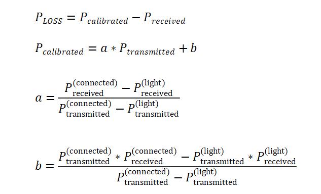
2.1.2 Power Calibration
To improve the effectiveness of the power loss detection method, the TX end can use power calibration to address the issue of system bias, but the premise of power calibration is that there are no foreign objects on the surface of the TX, which can be determined by using the Q value detection method.
As mentioned earlier, system bias is related to the transmission power level. In the ideal case, power calibration should be carried out in segments over the entire range of output power.
However, this method is difficult to implement, so a compromise solution is adopted: during the calibration phase, the TX and RX will determine their respective output and received power based on “light” load and “connected” load. Based on these two load states, the TX can use the following linear interpolation method to calibrate the output or received power.
2.2 What's Q Value Detection ?
Q value is the main parameter to measure the inductor, which refers to the ratio of the reactance and equivalent loss resistance of the inductor when it works under AC voltage at a certain frequency. The higher the Q value, the smaller the loss of the inductor.
The Q value of the TX coil can be affected by external environment, such as the presence of other metals on its surface, which will cause the inductance of the TX coil to decrease and the equivalent impedance to increase, resulting in a decrease in Q value.
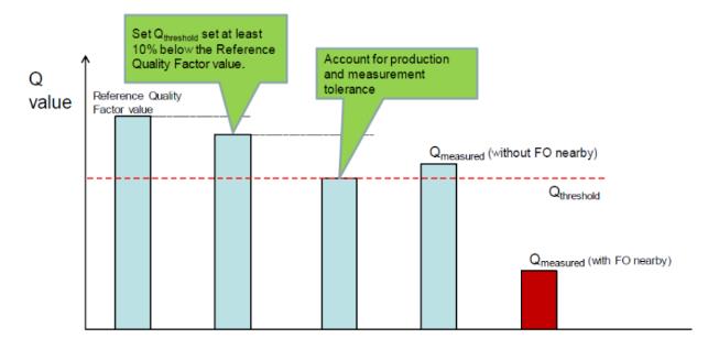
According to the EPP protocol of Qi, the TX must include Q value detection functionality during the negotiation phase to determine if there are foreign objects on its surface. In order to ensure that the TX can correctly determine whether the decrease of the Q value is caused by the RX coil or foreign objects, the RX should provide a reference Q value to the TX through packet 0x22, and the TX can determine a reasonable Q value tolerance based on that value, and compare it with the measured Q value to determine whether there are foreign objects.
2.2.1 The methods to detect Q Value
There are multiple ways to perform Q value detection, and while Qi provides a reference solution, it does not restrict its usage.
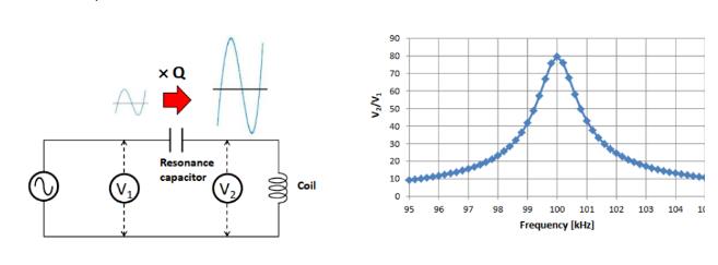
1) The following diagram is a reference plan provided by Qi.
As shown on the left side of the diagram is the principle circuit of the detection circuit, which includes a sine voltage source and a resonant capacitor in addition to the coil. When selecting the resonant capacitor, the reasonable working range of the circuit should be taken into consideration and the capacitor should be selected accordingly after determining the resonant frequency.
In this example, the resonant frequency is 100kHz and the Q value of the coil is the ratio of the effective voltage at both ends of the coil to the effective voltage of the driving power supply, that is Q=V2/V1.
2) The following diagram is a Q value detection solution used by NuVota, which is provided for reference.
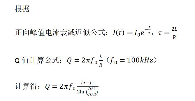
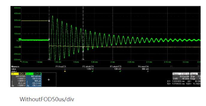
During Q value detection, the oscillation circuit is pre-charged by simultaneously turning on the S5 and Q4 transistors.
When the voltage reaches the preset value Initial, S5 is turned off and Q3 is turned on.
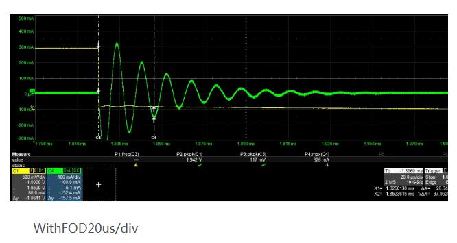
At this time, the current in the LC circuit will oscillate and gradually decay to zero. The presence of foreign objects will cause a change in the decay time of the current. Fixed threshold values Ith1 and Ith2 are taken, and ΔT is measured to calculate the Q value.
3. Summary
I hope this article will be useful for engineers working in the field of charging design, to help them achieve more accurate and efficient FOD detection. This will ensure that the products they designed are more reliable and give users greater peace of mind.
And, all of our wireless charging station products have FOD function to protect your devices.
If you think it’s helpful, welcome to share to your SNS network.