1.Introduction
Talking about chargers alone, there are compatibility tests, multiple-output tests, full-cycle charging tests, standby power consumption tests, conversion efficiency tests, ripple tests, temperature tests, and more. Leakage current tests will also be added later.
Today, we will discuss one of them in detail, how to test the ripple of a charger.
2.What is Ripple?
Taking mobile phone charging as an example, during the charging process of a mobile phone, electricity is converted from AC to low-voltage DC through the charger, and then transmitted through wires to reach the battery of the mobile phone. Among them, the electricity received by the mobile phone is DC, while the electricity from the socket is AC. The function of the charger can be simply understood as converting the AC from the socket into DC that the mobile phone can accept.
When AC voltage is converted to DC output through rectification and filtering, solid-state capacitors or electrolytic capacitors are used for filtering. By charging and discharging the capacitor, the output voltage is smoothed to achieve filtering. However, capacitors have internal resistance, and the current output by the secondary rectification generates a voltage drop on the capacitor’s internal resistance, superimposed on the capacitor voltage, and produces an AC component. At this time, the voltage peak value fluctuates slightly up and down with the cycle, so it is called ripple.
If the ripple is too large, it will affect the normal operation of semiconductor devices, causing touch screen drift, automatic clicks, and other interferences. In severe cases, it may even damage the device. Therefore, the ripple level is also an important indicator of measuring the output quality of the charger. Testing the output ripple of the charger can also help us understand the design level and material quality of the charger, and help us choose a reliable charger.
3.Equipment Required for Ripple Testing
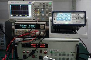
To complete the ripple test of a charger, some hardware equipment is required. In addition to the charger, a power supply, a load instrument, and an oscilloscope are also required.
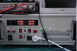
This power supply can be understood as a socket for household use. Unlike conventional sockets, this power supply can output different voltages and frequencies, providing different test environments for the charger. For example, the power supply can be adjusted to output 220V/50Hz, which can simulate the use of the charger in 220V mains; or it can be adjusted to output 110V or 90V, providing 90V and 110V outputs for the charger.
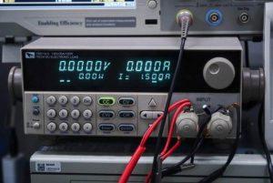
This is a load instrument, or an electrical device. If you don’t understand, you can think of it as a mobile phone or a laptop we use daily. The difference is that the power when charging a mobile phone or laptop is not continuously stable, and the role of the load instrument is to ensure long-term and stable power consumption, simulating the high-power output state of the charger. The load instrument we use supports a maximum load power of 150W.
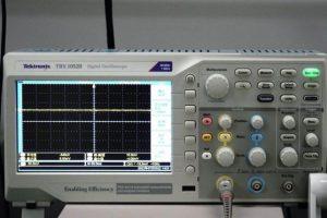
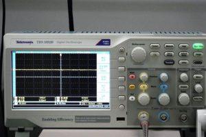
In addition, there is an oscilloscope, which acquires the input voltage information through its internal high-speed ADC, processes and amplifies it to display on the screen, and presents the ripple data of the charger in waveform and digital form in front of us.
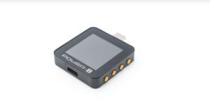
Finally, a POWER-Z tester is also needed, mainly used to control the output voltage of the charger.
4.How to test ripple data
To test ripple, a power supply, load, POWER-Z tester, and oscilloscope are all required. Connect the power supply, load, and oscilloscope, and yes, the power supply also needs to be connected to 220V voltage.
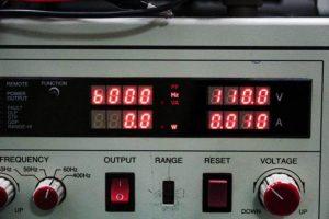
Adjust the power supply to output 110V 60Hz to simulate a 110V mains environment.
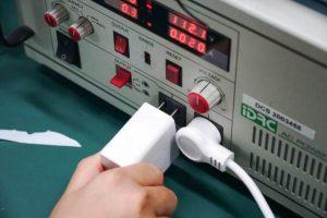
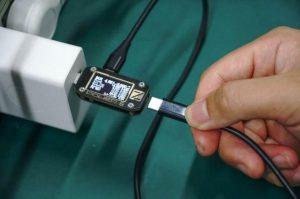
After everything is ready, plug the charger into the power supply output port.
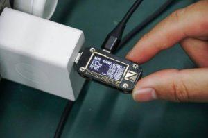
Then connect the POWER-Z tester to the USB-C port of the charger and open the spoofing interface. At this time, the PDO message of the charger has been read, and a 65W charger will be tested this time.
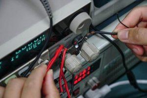
The load comes with positive and negative poles, connect two wires with self-contained clips to connect the charger.
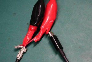
Cut open a 5A C2C fast charging cable, separate the positive and negative poles of the other end, and connect the positive and negative poles of the two wires separately. Note that after connecting, use electrical tape to wrap it to avoid a short circuit.
At this time, one end of the C2C cable is already connected to the load instrument, and the other end is plugged into the POWER-Z tester.
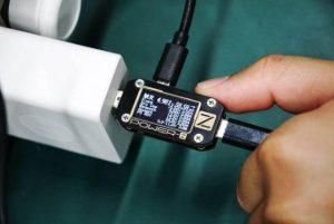
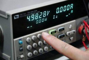
At this time, the POWER-Z tester will trick the charger into outputting 5V. Press the button on the upper right of the POWER-Z tester to adjust the output to 20V.
Finally, connect the oscilloscope probe to the load instrument’s terminal. At this point, a set of scenarios for testing the ripple of the charger has been set up.
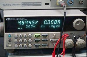
The test of the charger ripple is mainly divided into two parts: heavy load and no load. The no load is the ripple value when the charger is plugged into the socket and not used, and the heavy load is the ripple value when the charger is working and charging the device. From the display panel of the load tester, it can be seen that the charger is in the 5V output gear at this time, but there is no current, and naturally there is no power, so this is the no load state.
Looking at the oscilloscope, we can see that the peak-to-peak ripple at this time is 32mVp-p. This is the ripple data of the charger at 5V unloaded state. It should be noted that the peak-to-peak value of the oscilloscope ripple is constantly changing within a certain range, so a rough middle value needs to be taken as the unloaded ripple data.
Next, let’s use the POWER-Z tester to induce the output voltage of the charger to 5V.
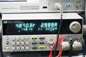
Click on number 3 to adjust the current to 3A, and click Enter to confirm the selection of 3A current.
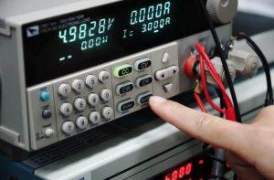
Click On/Off again to turn on the switch, and the charger will continue to output at 5V 3A 15W power.

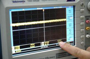
When outputting, use the oscilloscope to monitor the ripple of the charger. This is the final ripple value of the charger when outputting at 5V 3A 15W power. The other gears are similar, so they will not be introduced here.
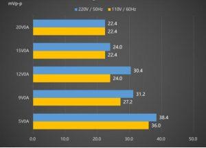
After collecting the test data, the above picture shows the ripple data of the charger in an unloaded state.
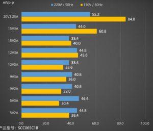
This is the heavy load ripple data of the charger under 220V and 110V mains input.
To summarize, the ripple test method introduced in this article is actually one of many test items for chargers, and the ripple data can reflect the materials and design level of the charger to a certain extent. It can show the AC component mixed in the DC output of the charger, and thereby judge the quality of the charger.